Product
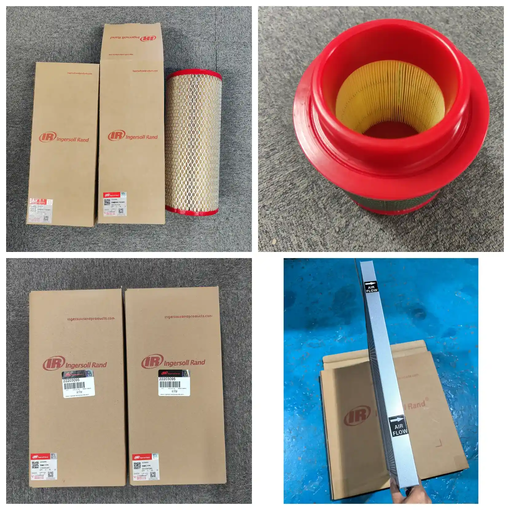
Ingersoll Rand 89874439 Air Filter Element | MSG Centrifugal
Ingersoll Rand 89874439 intake air filter element for MSG TURBO-AIR and MSG CENTAC centrifugal compressors. 215 mm OD × 110 mm ID × 188 mm height, approx. 2.0 m² media area, 5–10 μm filtration, ≥98% efficiency. Export-ready, serial-number verification supported.
- Export packaging & documentation support
- OEM / ODM customization available
- Sample and bulk order workflow
Product Overview
89874439 is the intake air filter element for Ingersoll Rand MSG TURBO-AIR and MSG CENTAC centrifugal air compressors. It installs inside the intake filter housing, upstream of the inlet guide vane and first-stage impeller.
Centrifugal compressors are 100% oil-free. Unlike screw compressors, there is no lubricating oil in the compression chamber to flush away particles. Any dust that enters deposits on the impeller, diffuser, and intercooler. Impeller fouling alters dynamic balance and aerodynamic efficiency; intercooler tube fouling raises interstage temperature and reduces overall efficiency. These units are typically continuous-duty prime movers (90–4200 kW), so unplanned downtime costs far more than the filter itself.
Replacement is judged without tools or disassembly: read the intake depression gauge while the unit runs. Green zone indicates remaining life, yellow zone means schedule replacement, red zone means the element is past its change point and the unit is running at elevated specific power.
Core Specifications
| Item | Value |
|---|---|
| Part number | 89874439 |
| Product name | Air Filter Element |
| Applicable series | MSG TURBO-AIR / MSG CENTAC centrifugal compressors |
| Construction | Dry pleated cartridge, single use |
| Quantity per unit | 1 pc (larger units use multiple elements per configuration) |
| Dimensions | 215 mm OD × 110 mm ID × 188 mm height |
| Effective filtration area | Approx. 2.0 m² |
| Filtration rating | 5–10 μm |
| Filtration efficiency | ≥98% |
| Recommended change interval | Approx. 2000 hours or 3 months, or when intake depression gauge enters yellow zone |
Technical Parameters
Filtration Performance
| Parameter | Value / Notes |
|---|---|
| Filtration rating | 5–10 μm |
| Filtration efficiency | ≥98% (for particles ≥5 μm) |
| Filter class | Not classified under EN 779 HVAC standards; centrifugal intake filters are characterized per ISO 5011 by efficiency, intake resistance, and dust holding capacity |
| Dust holding capacity | Approx. 600 g |
Centrifugal impellers have narrow blade passages and operate at very high speeds. Particles strike the impeller at far higher relative velocity than in a screw rotor. The same 10 μm particle has a more pronounced erosive effect in a centrifugal machine, and once intercooler tubes foul, cleaning requires shutdown and disassembly.
Flow and Resistance
| Parameter | Value / Notes |
|---|---|
| Rated air flow | Approx. 9 m³/min per element; actual quantity configured to unit intake volume, multiple elements in parallel |
| Face velocity | Approx. 0.075 m/s |
| Initial pressure drop | Approx. 0.5–1.0 kPa (approx. 50–100 mmH₂O) |
| Operating differential range | Approx. 1.0–3.0 kPa (approx. 100–300 mmH₂O) |
| Alarm / final resistance | Determined by intake depression gauge yellow zone; common engineering setting approx. 2.5–3.0 kPa (250–300 mmH₂O) |
| Pressure drop vs. energy | Each 1 kPa (approx. 100 mmH₂O) rise in intake depression increases specific power by approx. 1% |
Centrifugal capacity depends on intake air density. As filter loading raises intake depression, the pressure and density of air entering the first-stage impeller fall. To maintain discharge pressure and flow, the unit must increase speed or power, raising specific power — the energy consumed per m³ of compressed air produced.
By order-of-magnitude estimate, each 1 kPa increase in intake depression raises energy consumption by about 1%. For a 1000 kW unit running 8000 hours per year with depression 3 kPa beyond the change point, excess consumption is roughly 240,000 kWh per year — far more than the cost of a filter set. This is why Ingersoll Rand fits centrifugal units with an intake depression gauge as standard.
Dimensions and Installation
| Parameter | Value / Notes |
|---|---|
| Dimensions | 215 mm OD × 110 mm ID × 188 mm height |
| Construction | Pleated media, cartridge element |
| Effective filtration area | Approx. 2.0 m² |
| Pleat count | Approx. 106 pleats |
| Pleat spacing | Approx. 4.8 mm |
| Installation interface | Cartridge face seal, installed into intake filter housing |
| Seal type | Face seal (axial compression) |
| Net weight per element | Approx. 1.2–1.7 kg |
Procurement note: when cross-referencing replacement parts, compare all three dimensions — 215 mm OD, 110 mm ID, and 188 mm height. Centrifugal intake filters and screw compressor filters are not interchangeable; they are designed for entirely different intake volumes and face velocities.
Material Construction
| Parameter | Value / Notes |
|---|---|
| Media | Imported wood pulp filter paper (industry-common US HV or Finland/Sweden Ahlstrom media) |
| Media grammage | Approx. 130 g/m² |
| Inner/outer support | Galvanized steel perforated cage (inner support + outer guard), approx. 0.6 mm thickness, open area ≥45% |
| End caps | Metal end caps (galvanized steel) + polyurethane adhesive |
| Seal | NBR face seal ring |
| Adhesive | Polyurethane (PU) hot melt |
Operating Tolerance
| Parameter | Value / Notes |
|---|---|
| Operating temperature | −10 to +100 °C |
| Relative humidity | ≤80% RH, no condensation |
| Burst strength | Media burst strength approx. 200–400 kPa (per ISO 2758 paper burst test) |
| Collapse pressure | Element design differential pressure ≥4.5 kPa |
| Special features | No flame-retardant, anti-static, or moisture-resistant ratings noted for this model |
Service Life and Maintenance
| Parameter | Value / Notes |
|---|---|
| Service life | Approx. 2000 hours or 3 months |
| Actual change interval | Based on intake depression gauge yellow zone; shorten in coastal (salt mist), desert (fine dust), or high-humidity environments |
| Shelf life | Approx. 2–3 years (unopened, dry, ventilated storage) |
Applicable Standards
| Item | Content |
|---|---|
| Product standard | ISO 5011 (intake air filters for internal combustion engines and compressors — performance testing), evaluated by filtration efficiency, intake resistance, and dust holding capacity |
| Commonly cited test standards | ISO 2941 / 2942 / 2943 / 3723 / 3724 / 3968 |
| Standard applicability note | The ISO 29xx / 37xx series are general test methods for hydraulic transmission filter elements. If a supplier can only provide hydraulic filter standards, request ISO 5011 or the OEM specification sheet. |
| Oil-free certification background | The MSG TURBO-AIR / MSG CENTAC units this element serves are ISO 8573-1 Class 0 oil-free certified; intake filtration is the first line of defense in maintaining oil-free class |
Standard Maintenance and Installation Steps
Centrifugal work differs from screw compressor work: the impeller has rotational inertia, and the controller must confirm zero speed. Each job takes about 40–60 minutes; large housings may require two people or mechanical assistance.
- Shut down, confirm zero speed, lock out/tag out. Stop the unit and wait for the controller to confirm zero speed (centrifugal impeller inertia is high; do not judge by sound). Isolate main power and lock out/tag out. Criterion: controller shows zero speed and no abnormal inertial rotation noise.
- Locate the intake filter housing and release clamps evenly. The housing is upstream of the inlet guide vane. Release end cover clamps evenly in diagonal sequence. Criterion: on large housings, support the end cover before the last clamp is released to prevent sudden drop damage.
- Remove the old element and inspect the housing for dust tracks. Pull out the old element (use mechanical assistance for larger sizes). Focus on the inner housing wall for dust tracks. If present, the seal has bypassed and unfiltered air has entered downstream. Criterion: no dust tracks on the inner wall means good sealing; if tracks are present, check both the seal land and end cover flatness.
- Inspect the seal land. The seal land must be clean, flat, and free of corrosion pitting. Criterion: no burrs or unevenness by hand. On a centrifugal machine, any micro-bypass means unfiltered air with particles directly enters the first-stage impeller — this step is non-negotiable.
- Install the new element and confirm seating. Press 89874439 into the housing until the seal land is fully compressed and seated; confirm the element is centered, the seal is evenly compressed, and there is no skew. Criterion: even compression marks around the seal land.
- Reinstall the end cover and check the depression gauge impulse line. Reinstall the end cover and tighten all clamps (diagonal, even, in stages). Before startup, confirm the depression gauge impulse line is clear, not blocked, and not frozen. Criterion: line is clear; a blocked impulse line gives a false clean reading and lets the element run past its change point.
- Start per centrifugal startup procedure and verify. Start per the unit's specified procedure. After stable operation, read intake depression; it should return to the clean-element baseline range. Listen for air leaks at the housing. Criterion: depression reading in green zone, no abnormal noise; record date, running hours, and depression reading.
Centrifugal-specific rule: the danger of seal land bypass is amplified in centrifugal machines. A screw compressor still has oil to carry away some particles; the centrifugal compression chamber is oil-free, so all particles deposit on the impeller and coolers. A single seal failure can cost an impeller dynamic balance correction.
FAQ
Which machines use 89874439?
Ingersoll Rand MSG TURBO-AIR and MSG CENTAC centrifugal air compressors. These two series span a wide range (90–4200 kW), so exact fitment requires the unit nameplate and serial number cross-referenced against the centrifugal parts catalog.
How do I decide in five minutes whether to replace?
Read the intake depression gauge while the unit runs: green zone means remaining life, yellow zone means schedule replacement, red zone means past the change point and immediate replacement is required. No disassembly or tools needed.
Why read the gauge instead of changing by time?
Dust loading varies greatly by location — salt mist in coastal areas, fine dust in deserts, process dust in industrial zones — and by season. Fixed calendar intervals either waste filter life or let the machine run past its change point. The depression gauge reflects actual loading, not assumptions.
What if the gauge is broken or the reading does not move?
A stuck gauge is a common failure point. Check needle return at every service. If the gauge has failed, change the element on a conservative time interval until the gauge is repaired — do not judge by feel.
How much does filter loading affect centrifugal efficiency?
Rising intake depression lowers intake density. To maintain pressure and flow, the unit must increase power, raising specific power. By order-of-magnitude estimate, each 1 kPa increase in depression raises energy consumption by about 1%. Centrifugal units are often megawatt-class continuous-duty machines, so the electricity cost is significant.
Can I blow it clean with compressed air and reuse it?
No. This is a dry, single-use element and is not designed to be cleaned. Reverse blowing with compressed air damages the media fiber structure and creates invisible channels that let unfiltered air pass — more dangerous than not changing the element at all.
What else should be checked when changing the element?
The inlet guide vane linkage, intake silencer, and intercooler tube bundles. For water-cooled units, also check the cooler water side for scaling, which directly affects interstage temperature. Also verify the depression gauge impulse line is clear.
Can this element be used in a screw compressor?
No. Centrifugal intake elements are designed for high-flow continuous intake duty. Dimensions, area, and resistance characteristics differ from screw compressor elements, and the two are not interchangeable.
How long does stock take to ship?
Regular stock ships within 24 hours. Southeast Asia approx. 3–7 days, Middle East approx. 7–10 days, Africa and Latin America approx. 10–18 days, Russia/Belarus approx. 10–15 days. Exact timing depends on stock and sailing schedule at time of inquiry.
How do I confirm 89874439 is correct with 100% certainty?
Three steps: ① Check the unit nameplate to confirm it is MSG TURBO-AIR or MSG CENTAC; ② Provide the unit serial number for cross-reference against the centrifugal parts catalog; ③ If the old element is still available, read the part number directly from the element body. Step ③ is the most reliable.
Compatible Models
Fits Ingersoll Rand MSG TURBO-AIR and MSG CENTAC centrifugal air compressor series. Common model families are listed below for identification (exact fitment confirmed by serial number):
MSG TURBO-AIR Series
| Model Group | Models |
|---|---|
| TA / NX Series | MSG TURBO-AIR NX 2000, NX 5000, NX 8000, NX 12000 |
| TURBO-AIR standard models | 1500, 2000, 2040, 3000, 6040, 20000, 30000 |
| TURBO-AIR COOLED | COOLED 2000 |
| TURBO-AIR API | API models |
| LMAC Series | LMAC 20, LMAC 30, LMAC 50 |
| TURBO-GAS | TURBO-GAS 2040, 6040 |
MSG CENTAC Series
| Model Group | Models |
|---|---|
| C Series | C400, C700, C700e, C1000, C2000, C3000 |
| Multi-stage designations | 3CII, 5CII |
Other MSG Series: MSG 2/3, MSG 4/5, MSG 8/9, MSG 12/14/16, MSG 18, MSG 25
- The table lists the MSG centrifugal family for identifying whether your unit falls within this element's applicable range; individual fitment must be confirmed by serial number.
- TURBO-AIR and CENTAC differ greatly in intake volume and housing size; a single unit typically uses multiple elements, quantity depending on model.
- If you are unsure which series your unit belongs to, provide a nameplate photo and we will cross-reference by serial number.
⚠️ Model applicability note: This part number applies to Ingersoll Rand MSG TURBO-AIR and MSG CENTAC centrifugal air compressors. Before ordering, please confirm: ① your unit is an Ingersoll Rand MSG series centrifugal compressor; ② the number on the old element body matches the part number you are purchasing. If your unit is another brand or model, please advise and we will verify dimensions and fitment.
Related Components
Seven components in the centrifugal intake and lubrication system are maintained on the same cycle as the air filter. Listed below by location, function, and inspection point. For specific part numbers, refer to the unit's centrifugal parts manual.
| Component | Location | Function | Inspection Point |
|---|---|---|---|
| Intake depression gauge | On the intake filter housing | Indicates element loading; the sole authoritative basis for element replacement | Check needle return at every service; impulse line must be clear and not frozen |
| Inlet guide vane assembly | Downstream of filter, upstream of first-stage impeller | Regulates intake volume and angle for capacity control | Check linkage for binding or looseness; vane fouling affects control accuracy |
| Intake silencer | On the intake duct | Reduces intake noise; on some models also acts as flow straightener | Check for corrosion perforation or loose silencing material |
| Intercooler tube bundles | Between compression stages | Reduces interstage air temperature; key to centrifugal efficiency | Check air side for fouling; on water-cooled models also check water side for scaling |
| Aftercooler | After final stage discharge | Cools discharge air to set temperature | As above; tube blockage directly raises discharge temperature |
| Intake hose and housing seals | Between filter housing and intake duct | Ensures intake path is leak-free with no unfiltered air bypass | Check for cracks, aging, loose clamps; bypass leakage is as harmful as no element on a centrifugal machine |
| Centrifugal compressor lubricant | Gearbox and bearing lubrication system | Lubricates gears and high-speed bearings, isolated from compression chamber (unit is oil-free) | Test oil per unit requirements; monitor gearbox oil level and temperature |
Recommended companion service: centrifugal maintenance value centers on efficiency retention. When changing the intake element, also inspect the intake depression gauge, guide vane mechanism, and intercooler condition to make full use of the shutdown window. Cooler cleaning and impeller inspection should be scheduled in the annual maintenance plan rather than waiting for a noticeable efficiency drop.